DIY Arduino
From trash to arduino
It was 2016, I was in my phase of taking apart old electronics to scavenge parts. My family liked to poke fun that I had accumulated bins of various resistors, switches, capacitors, transistors, LEDs—you name it. But guess who they called when something broke? I've saved a ton of money over the years replacing dead resistors in car radios or broken switches in microwaves, all thanks to those parts bins.
The Discovery
One day I cracked open the chunky 12V cigarette lighter plug from an old car GPS unit. Remember those? Inside the plug was a tiny board with a chip labeled Atmega3280MU.
That caught my attention. I recognized it,my 3D printer's motherboard used an Atmega3280, and it's the same family used in Arduino boards. So I thought why not build my own Arduino?
The Challenge: QFN Soldering
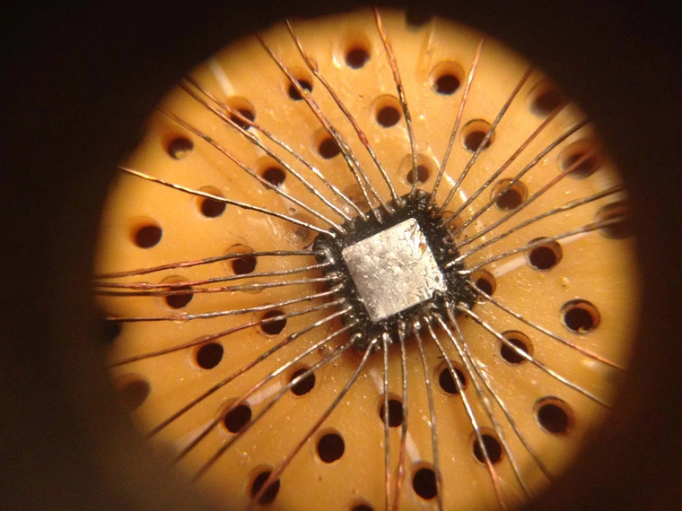
The Atmega3280MU I found was a QFN package with a 0.5mm pitch. That's means there's only 0.25mm of space between each pad.
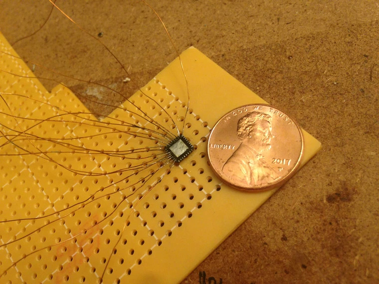
I didn't have a breakout board or access to proper reflow tools, but I did have a hot air soldering station and some 32AWG enameled magnet wire. At just 0.2mm thick, the wire was thin enough to fit directly onto the tiny pads of the QFN chip.
So I sanded the enamel off the tips, and using a piece of a disposable camera lens as a magnifying glass, I soldered a wire to each pad by hand.
This was probably my greatest achievement to date.
It was so fragile that I immediately glued the back with hot glue to keep the wires in place. That also let me thread them through a perf board.
Assembling the Board
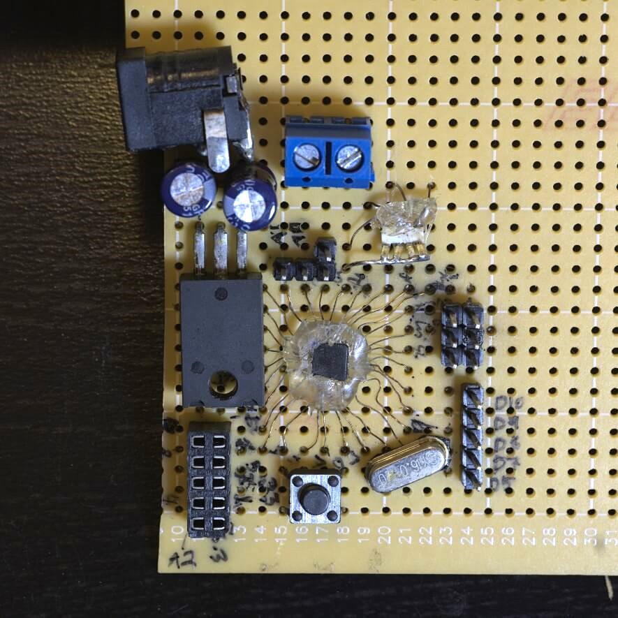
I looked up the pinout of the chip and found a basic Arduino circuit schematic. I scrounged up:
- A voltage regulator (pretty sure it was an LM7805)
- Some capacitors and resistors
- A crystal oscillator
- LEDs for power and blinking
- And an ISP header to program it
I didn't have a USB interface chip, but I did have an ISP programmer to talk directly to the Atmega's through the pins.
And It Worked!
The red LED indicates power. The green one shows the classic Arduino "Hello World", a blinking LED.
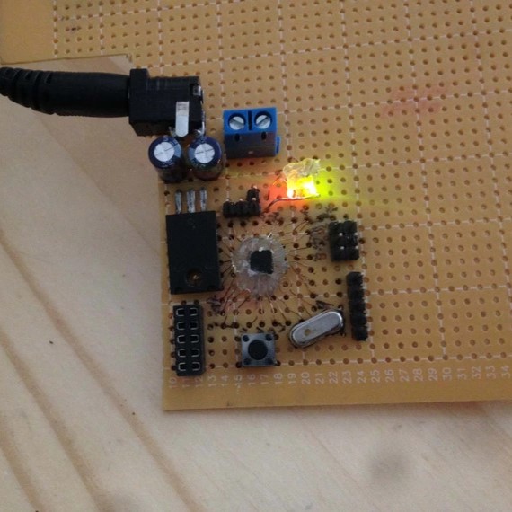
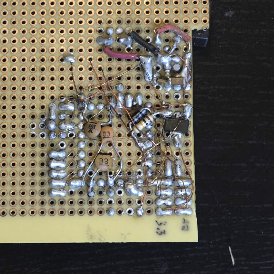
This little board, cobbled together from scraps and soldered under a microscope, booted up and blinked. No fancy PCB, no pre-assembled modules. Just many hours of squinting and resoldering accidentally bridged pins.